
Welcome, from sunny Australia!
The Valve Gear
The Valve Gear
Modern twin cams have excellent valve
gear, and so are often best left standard. There are mainly two systems
used to control the valve clearances - Ones with the shim adjuster under
the follower bucket, and the other where the shim sits on top of the
bucket, eg, Toyota 4AGE. The only advantage the shim-over-bucket system
has is that it's very easy to change the valve clearances without having
to take anything apart. (Like the shim-under-bucket system requires)
Problems start with big cams. A typical
standard cam might have a duration of 230° from seat to seat, and
you'll start to make interesting power as the duration climbs above
~270°. A full race cam might go as high as 320° duration (or
even more on some), but if the engine is properly tuned it can still be
driven on the road with great success.
Some cam grinds will have a larger amount
of lift than the standard cam, and while no-one denies that more lift
will give you more power, I don't believe that for road & club use
you need a great deal of lift, ie, 0.350" lift is normally a pretty
small figure for a performance engine, but with a multi-valve twin cam
that is quite often plenty. You'll still get an increase of power with
increasing lift, but at a rapidly decreasing rate, and at a rapidly
INcreasing rate of unreliability. I've seen some Group A 2 litre touring
car race cams with 0.550" lift - The valve springs have to be changed
every 2 hours ...
For what it's worth, the cams in the 4AGE in
my AE-86 road car have 0.290" lift and it makes 100hp per litre - Not
bad. A good rule-of-thumb for max valve lift is to have the max lift about 1/3 the diameter of the valve.
One very important factor with camshafts,
apart from the duration and lift, is the lobe centre angle. From what
I've experienced with my own engines and also noticed by talking to a
lot of other people around the world is that with cams smaller than
about 270° - 280° duration, you want the lobe centres to be
around the 110 - 110 mark, and with bigger cam the lobe centres at
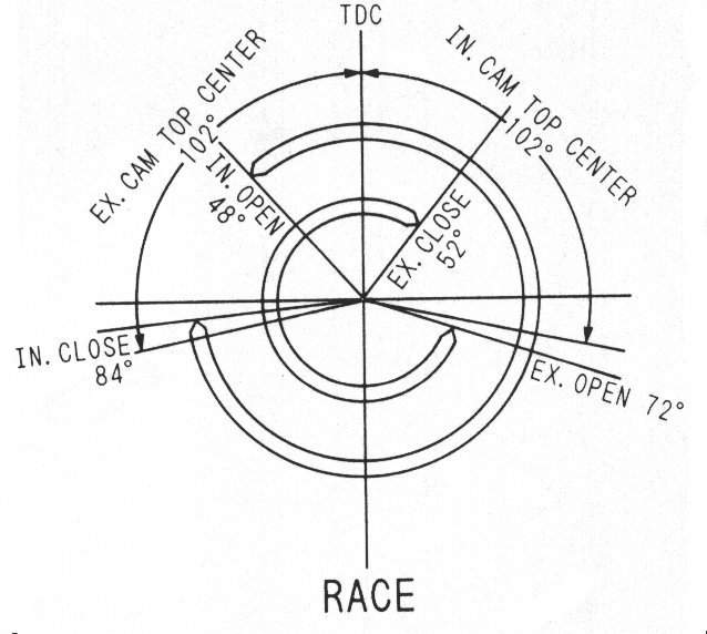
around the 100 - 100 mark. To explain what I mean by '100 - 100', I have
copied some text from my 4AGE Mods page and
reproduced it here ->
To get accurate cam timing like this can
be done with standard cam pulleys, modified by drilling new holes in
the
right spot after the new timing has been determined. Shown in the
pictures below is the other two methods used to give adjustable cam
timing, one of which is vernier adjusters and the other slotted cam
pulleys. Both are pretty easy to make, but only the slotted type can be
adjusted with super-fine accuracy.
(The vernier type has, say, ten holes
drilled in the camshaft front flange and nine hole in the cam pulley. As
you turn the cam pulley and cam around each other, the holes line up in
different places so you can often find such an alignment very close to
where you want the cam to be. But with the slotted type you can get the
timing absolutely spot on. The slotted type are easy to make if you have
access to a lathe, but they can also be bought for a reasonable price)
Another important thing to note is that
the closer to 100-100 timing you get, the less and less inlet manifold
vacuum you'll be getting, to the more likely the standard computer (and
aftermarket, for that matter) will be unable to sense that vacuum
properly, thus making the engine run badly and use too much fuel. The
other effect is that the engine will start to idle roughly, compared to
the 110-110 timing. (see later paragraphs on flywheel inertia and inlet
manifold for further info on this, however)
As an example of how a 4AGE idles with
100-100 cam timing, 288° cams, and a stock inlet manifold, have a
listen to my AE-86. Like a rotary, huh? :)
|
Inlet port -
|
Lift | CFM |
| 0.060" | - 31.5 | |
| 0.120" | - 65.0 | |
| 0.240" | - 108.4 | |
| 0.300" | - 111.1 | |
| 0.360" | - 112.5 |
So you can see that past about 0.300"
lift there is little to gain with a fairly standard head set-up. To get
a lot more you'll need a lot of work done to the head. A good
rule-of-thumb is that you only want to lift the valves to a maximum of
about 1/3 of their diameter.
Another good rule of thumb is one that
derives from the CFM of the head - If you take the CFM @ 10" of water,
multiply it by the number of cylinders, and then multiply by 0.43, then
you'll get a fairly accurate estimate of how much power your engine will
make. (Note that the rest of the engine has to be matched with the head
to make the equation work properly) So, for the 4AGE engine I've just
mentioned above, it should make about 191 hp with 0.300" lift cams. Note
that this rule-of-thumb doesn't allow for other restrictions in the
inlet manifold, etc. To get a better picture you really have to flow the
head with the entire inlet manifold, etc, attached. In the above
example, the end result would most likely me more like ~100 CFM.
The other problem you may run into with
bigger cams is that if the lobe is big enough then it will hit the part
of the head surrounding the bucket. If this is the case, then it's quite
ok to remove some of the material there to let the lobe pass clearly.
Another myth passed on from two valve
engines is that you need high static spring pressure to stop the valves
from bouncing & floating at high revs. Since the valves are so small
in a multi-valve twin cam, you can quite often run very low seat
pressures, eg, 30lbs or so, and have no problems even 8,000+ revs.
You'll also gain power by not making the engine have to push the valves
open against such a high resistance, and also generate less heat that
way too.
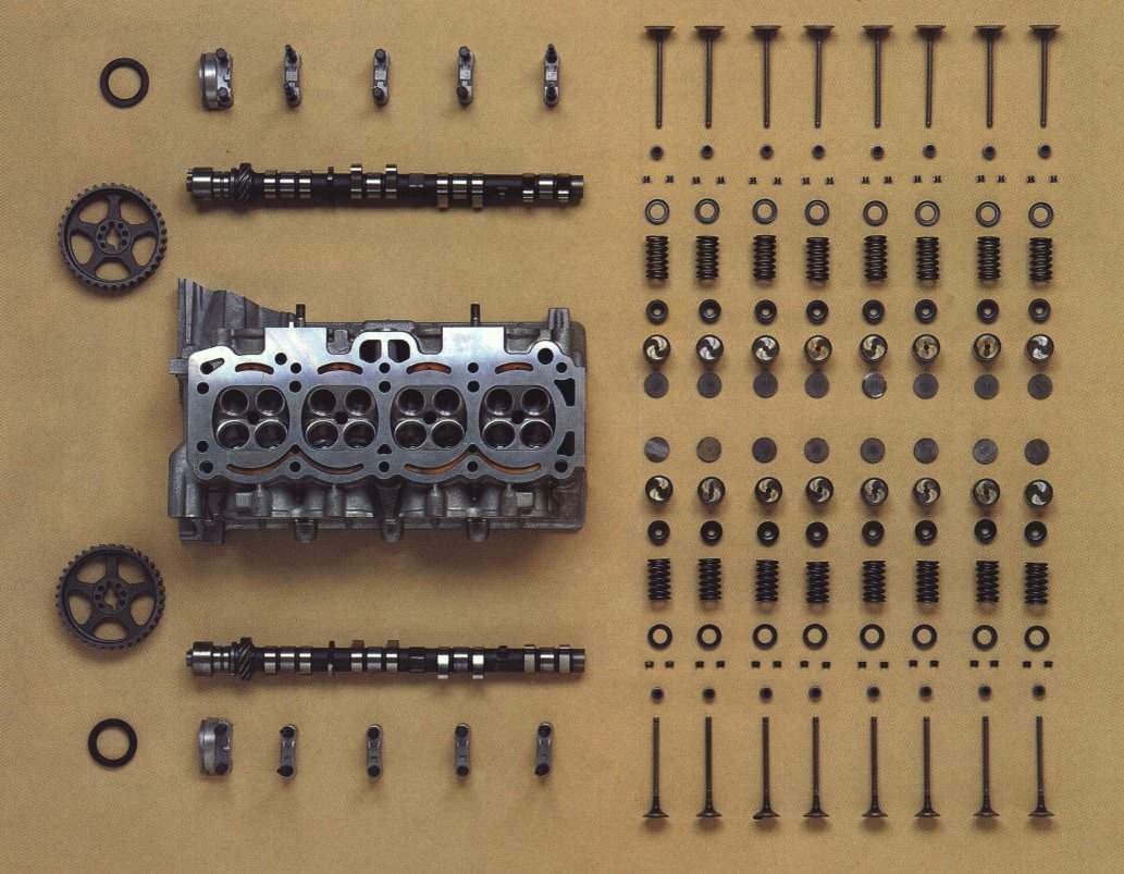
You may notice that the valve springs have
one end with the coils wound closer than the other. This end goes
against the seat and the other to the retainer - It's made that way to
reduce spring harmonics.
At the front of the cams there is a oil
seal. The only trick with these is not to push them in too far after
fitting the cams to the head. With most engines, the seal needs a gap
behind it so the oil can get out from the front of the cam without
having to go the wrong way - Through the seal! (ask me how I
learned that one ...)
One of the most significant things you can
do to the engine is to alter the cam timing. Rarely is the standard cam
timing either correct or desirable. Even more so with aftermarket cam
profiles. The biggest change in power delivery is noticed by moving the
inlet cam - By advancing the inlet cam you will move the peak power
point lower down the rpm range, and vice versa. (Two systems are
currently in use to change the inlet cam timing actively, while the
engine is running. One is the Toyota VVT, or Variable Valve Timing
system, that has a small hydraulic device on the front of the cam to
alter the timing as the engine's computer instructs. This system alters
the valve overlap, not the total cam duration. The other is the Honda
Vtec system, which has a similar device that moves a set of cam
followers so that different cam profiles run on those followers, thus
changing the timing and duration. Read a comparison on the two here.)
To make it easy to change the cam timing,
there are a couple of ways of doing it. Both involve some machine work,
but the easiest, though technically most difficult is to make the cam
and cam pulley a 'vernier' set-up. To do this you must drill a number of
equally spaced holes in the front of the cam and the cam pulley where the
locating pin runs through. The trick is to have a different number of
holes, eg, nine in the cam and eight in the cam pulley. This means that
to make the holes line up you'll have to look around to find a point
where the holes line up so you can fit the locking pin. The other way is
to cut the centre out of the cam pulley (Leaving a stub of the spokes on
the outer edge about 1/2" wide) and machine a disc of alloy (Which has
a hole drilled in the centre to fit the main cam bolt through and a
smaller hole for the locking pin) to neatly fit into the centre of the
cam pulley, with machined slots to allow bolts to go through to the stubs
of the cam pulley spokes. The slots will allow you to move the alloy
disc in relation to the out toothed part, and so adjust the cam timing
very quickly and easily.
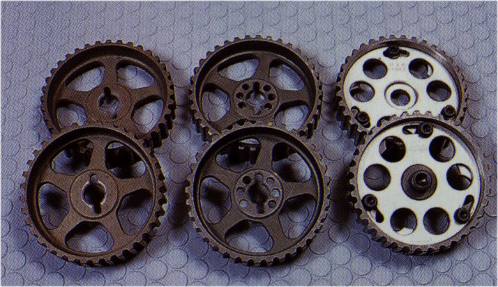
Here's a pic of a standard cam pulley, (on
left) a vernier cam pulley, (middle) and a fully
adjustable one.
If the cam belt has a cover over it, you
may want to remove it to help keep the belt running cooler and so you
can see what condition the belt is in far more easily.
Continue on to -
Crank, con-rods, and
pistons - The block - Other stuff - Other
Tuning - Further reading and race car sounds
For more motorsport links, try the motorsport section on my links page.
Back to the Index page
Page & contents where applicable © Bill Sherwood