
Welcome, from sunny Australia!
Some car & engine performance - Theory & practice
Some car & engine performance - Theory & practice
I tend to ramble on a bit, so you may not
find a lot of this stuff very interesting! But if you do, then please
read on and hopefully enjoy it. (I'll try to keep it all short, and so
some of my explanations are all too brief, unfortunately) I will
only be talking about fuel injected twin cam, multi valve engines as
they are rapidly becoming the dominant type of engine. Turbo's and
superchargers get a brief mention as well.
Disclaimer!! - All the mods I describe here, so whilst I certainly
recommend them I take absolutely no responsibility for them, ie, if they
don't work then don't blame me! They've all worked on my machinery, so
if you have trouble, email me to
let me know what the problem is and I'll see if we can work it out.
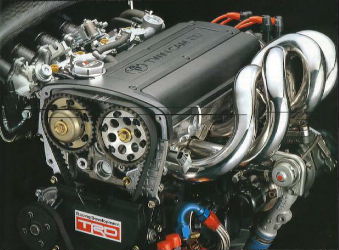
Here's a picture of the
sort of thing I like playing with, given the chance. It's a Toyota 4AGE 1.6
litre, 20 valve, (3 inlet and two exhausts per cylinder) turboed engine.
I don't have any power figures or info on it, but I'd guess it'd be well
over 300 horsepower. Yum!
On this page, you'll find info on the Inlet system
These links below will take you to a new
page -
Combustion Chamber
Exhaust
The Valve Gear
Crank & Con-rods
& Pistons
The Block
Other Stuff
Other Tuning
and
Further reading and
race car sounds
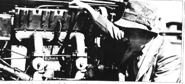
First off, some history. The origin of the first twin cam four valve-per-cylinder engine may surprise you. It was conceived by an Englishman, Ernest Henry, who worked for Robert Peugot, (Of Peugot car building fame) and came to life in June 1912! The engine was a 7.6 litre four cylinder. One of them was imported to the US in 1913, and run by "Wild Bob" Burman. In 1915 it was rebuilt by Harry Miller, who then went on to build a very successful range of racing engines that eventually resulted in the famous Offenhauser range of racing engines. All subsequent multi valve engines originated from that early Peugot, and I have managed to find a rare photo of the one that was imported to the US and run by (and renamed) by Bob Burman. Take a good look at the photo - Just about every performance engine you've ever seen or will see came from this very engine.
ENGINES -
An engine is basically an air pump, so the
more air you can get the engine to pump the more power it'll make. That
is the start and finish of the objectives of increasing your engine's
performance!
So, how to get more air moving through the
engine?
Inlet
- Let's start at the beginning - Air gets sucked into the air inlet.
It's very important to suck the air from the coldest place you can find.
(This may not be under the bonnet) Cold air gives more power than hot
air because of the greater oxygen content for a given volume. A rough
rule-of-thumb is that you'll get an increase of 1% power for every
2°C temperature drop. To find the coldest place, you may have to
suck air from one side of a headlight, or perhaps from under the
mudguards, etc. Another very important consideration is to make sure
that the inlet pipe doesn't sit in a place where it will get heat soaked
when the car isn't moving. (Even more important for turbo cars.) It's
also not a bad idea to try to get some ram effect from the cars
forward speed - But don't make the inlet so that it sucks the rain
straight in. The ram effect on a road car is very small though, and not
worth the effort if you have to make big changes to make all the new
air-plumbing fit in.
Next in line is the air cleaner. There are a
number of different types available, but they basically boil down to two
types - Oiled foam and convoluted paper. I prefer the foam type because
they can be custom made for any application and can also be cleaned
& reused many times.
In between the air cleaner and the head
there is the inlet manifold, and quite often there is some bends in the
tracts of the manifold pipes to get to the head. The best way to make
the pipes go around corners is to flatten the pipe (Make it
wider at the same time so the total area of the cross-section of the
pipe doesn't decrease) The pipe should end up narrower going in the
direction of the bend- This allows the air going around the bend to
flow
more smoothly as there is less difference in the distance between
the outside and the inside of the pipe, so there is less
turbulence
generated in the bend.
There is some debate weather or not it is
worth polishing the inlet tract and inlet ports. Most engines these days
have a light sand cast finish to them, and I believe that this is close
to the optimum for creating a good boundary layer, which makes for a
more effective inlet system. The best finish seems to be the one left by
a 400 grit sandpaper. The other school says that there is not time for
the boundary layer to form and so a highly polished manifold & head
is the go. I believe that most dyno tests show that a slightly roughened
surface gives more power in most cases, so in that case I don't think
that it is worth the cost and effort to polish the inlet manifold and
head at all. Simply clean up the casting 'dags' that are always
present.
Most modern engines have single throttle
body which is quite large enough for any reasonable mods, and so
refitting the engine with a larger one is not necessary.
It is well worth matching the inlet manifold
with the head because of the need to keep any ridges or lips away from
the area so close to the inlet valves. You may also want to consider not
using a gasket between the manifold and the head to minimise the gap
they would normally have. Use a thin layer of high quality silicone
gasket sealer instead. (Make sure the gasket didn't block off any water
passages though)
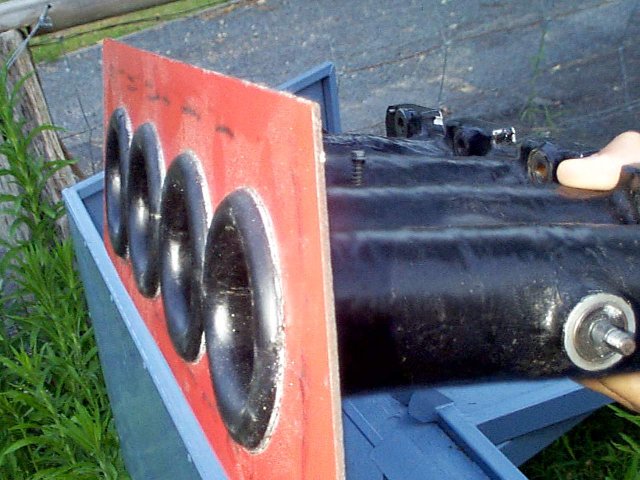
For those of you lucky enough to be able to
have proper inlet trumpets, you can improve the flow into those by
fitting a flat plate just behind the trumpet bell and rounding off the
bell so that it smoothly blends into the flat plate. The reason is that
most of the air comes in the trumpet from the sides on the induction
stroke rather than in line from the front as you'd expect, so if the
airflow has to pass over sharp lip of the trumpet it will generate
turbulence. If it has a nice, smooth bump to go over then little
turbulence will be generated. Here is a picture of an EFI inlet
manifold that used to be on my racing car when I ran fuel injection on
it, showing the smooth lip I've just described -
The inlet port is a rather critical
beast. In the modern engine is it usually best left alone, or maybe some
minor mods to improve the airflow through the port and valve. Quite
often you can make some improvements by making the area just above the
valve (including the exhaust) 90% the size of the valve head, ie, if the
valve is 30mm diameter, then about 3mm above the valve seat should be
27mm in size. This is the optimum for the venturi effect the inlet port
needs. The port in this area should be as straight as possible for as
long as possible, ie, you want at least 12mm or so (on the 'bottom' of
the port) before the port turns into the direction of the inlet
manifold.
The port divider between the valves should
also be left slightly rounded and not ground to a sharp edge.
The port width should be narrower than the
distance between the far sides of the inlet ports, by about 10% or so to
improve inlet swirl. It is super critical to make the induction air
swirl as it goes through the inlet valves to get the best airflow! Most
of modern car makers have very well shaped ports, so little work is
needed in that area. (As an example, to get a push-rod 1300cc 3K
Corolla head to flow over 140hp would cost about $1500 in labour and
parts, but to get a modern 1300cc twin cam to flow about 200hp can cost
about $500)
Some head shops will cut the inlet valve
guides down so that nothing protrudes into the inlet port, but there is
no need to go to that degree and in fact it can be detrimental to the
airflow. What can be of benefit is to reshape the inlet valve guides so
that they are teardrop shaped to minimise turbulence in the port.
One excellent test is to test the airflow
with the inlet valve in the head and then without. If you have done your
job properly then the head will flow more air with the valve IN PLACE
rather than out.
Another common myth is that larger valves
are needed to make lots of power, but again quite often the standard
valves are more than adequate.
A few years ago, I came across an old
magazine that had an excellent diagram in it that lets you work out how
long you should make your inlet port length. That is, the length from
the middle of the inlet valve to the end of the inlet trumpet.

For more motorsport links, try the motorsport section on my links page.
Back to the Index page
Page & contents where applicable © Bill Sherwood