
Welcome, from sunny Australia!
My New Racing Car pics & details
My New Racing Car pics & details
My Father and I have
decided that we have
nearly reached the end of the development of my current car - though
it's still a quick car - and so the only way to get significantly more
speed from it is to simply build another one. The class of racing in
the
UK has very similar rules (apart from the engine size and other minor
details) and so we can use a chassis design similar to that used in the
UK in Australia with only minor modifications to suit the local rules.
That chassis is a Mallock Mk31, the last of the front engined Mallocks.
Virtually all of the current
running gear
will be taken out of the 'old' car, as it's very reliable, light, and
is
of high quality.
| There are currently another two other Mallock Mk31's in Australia, one of which was originally owned by Phil Shaw in Sydney. Most of the pictures of the car below are of his car, though mine will be quite different in some areas, especially visually.. |  |
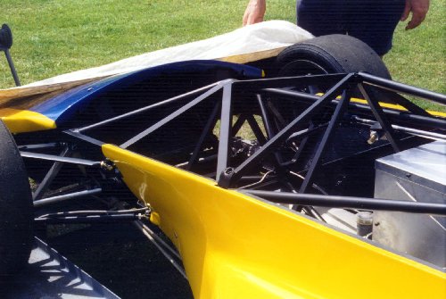 |
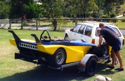
This is Phil's car - You see the removable bar in place in this picture. This photo was taken when the car was a bare chassis, and was on its way to Sydney from Brisbane to get finished for the 1997 Sports 1300 Nationals. The engine, gearbox, etc, still had yet to be fitted. (The meeting was only 3 1/2 weeks away!) |
| A view of the drivers cockpit area. Still a lot of tubes in the chassis! The tall points on the chassis give it's nickname of a 'cathedral' chassis. They work very well, and have a torsional rigidity of about 8200 ft-lbs per degree of flex. To give you an idea what a more conventional car is like, most of the Lotus Super Seven clones would have around 500 ft-lbs per degree! |  |
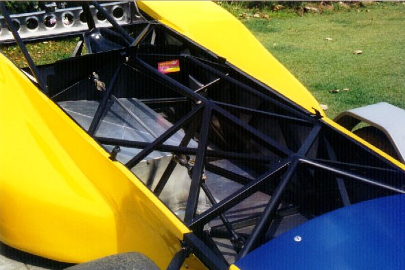 |
In this view you can see the aluminium box that the drivers legs sit into keep them separate from the engine compartment. |
|
Here
is the view
from behind the drivers head, down across the car.
|
 |
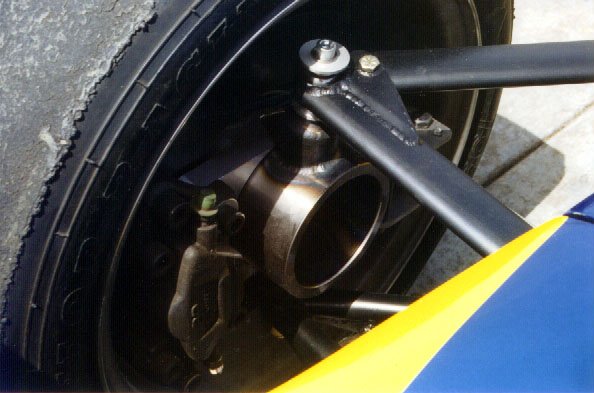 |
The front right hand wheel and upright. Note the fabricated upright, which uses a 'live axle' type hub instead of the more common fixed type as on road cars. On this type of hub, the axle that the wheel bolts onto rotates with the wheel instead of being fixed to the upright. This a a much lighter and stiffer way of mounting the front wheels. |
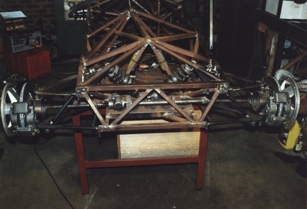
| This is a good view of the fabulous Mumford Link rear end. The Mumford is the only lateral link you can have on a live axle rear end type suspensioned car that lets you have the roll centre as low as you'd like, for example it's possible to have it underground. | 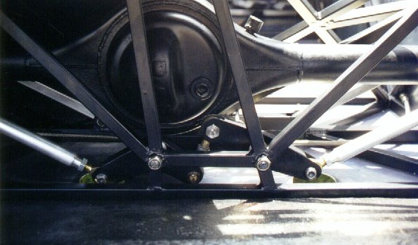 |
 |
A good view of the rear end of the car. The large wing on the back has yet to be fitted to the two fibreglass uprights that support it. That's my Father leaning over the front of the car, having a look at the suspension & uprights, and no doubt scheming away ... :) |
A bit of an update
 |
Here's some newer pictures of the car, taken in late 2000. You can see that the suspension is basically done, and so are the brakes. What's harder to see is the engine & gearbox mounts that're also done. If you look carefully at the right hand picture you can see the rockers for the front suspension, and how they connect via a push-rod to the springs/dampers. | 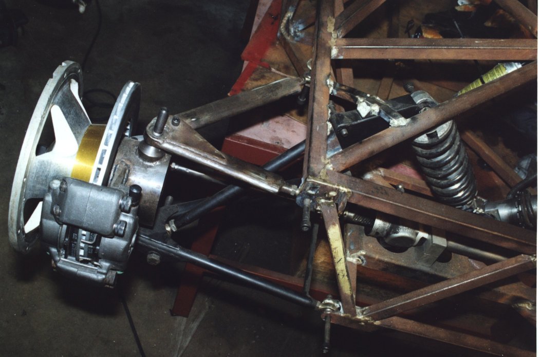 |
 |
Here's a couple of close-ups of the front hubs & brakes. On the left you can see the very large (for the size of the car) front brakes, and also the fabricated front upright. On the right you can see the front suspension and rocker assembly. | 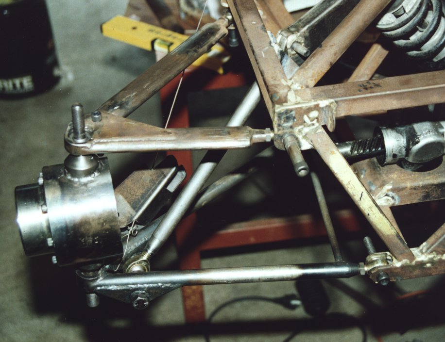 |
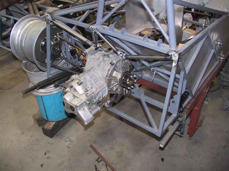 |
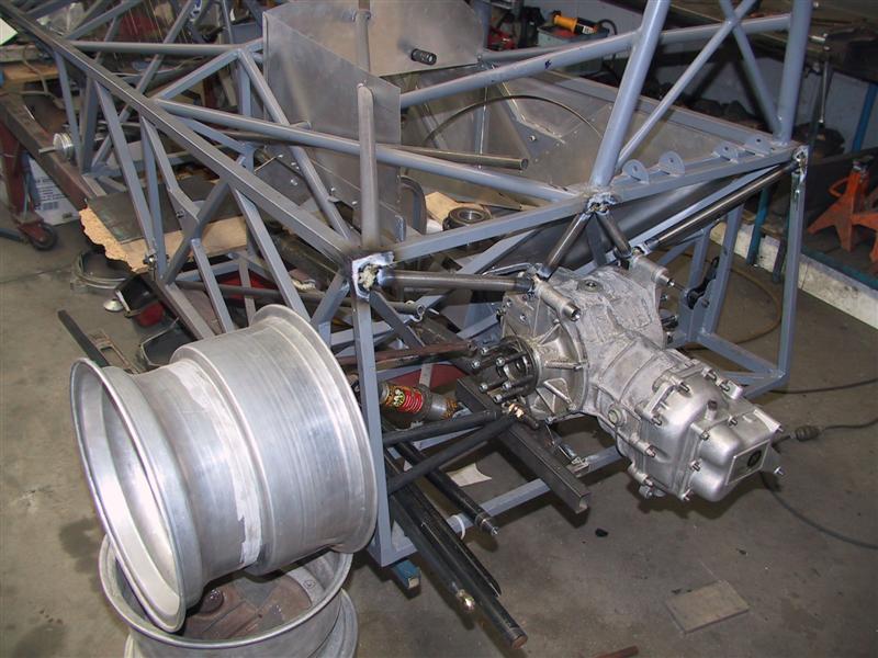
The
big job of fitting the Hewland transaxle to the rear of the Mallock has
begun though, and in the two pictures here you can see the tubes
connecting the gearbox to the spaceframe chassis. The bell housing will still contain the clutch, but the tailshaft will be in front of the gearbox instead of behind, as is typical in RWD cars. The are a lot of little problem to solve, such the gear linkage, etc, but we will work through them as they come. |
 |
Late November 2003
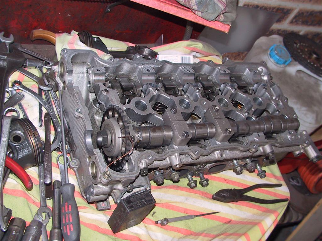 |
Not a lot more
done, but the engine
for the car is in the workshop and here's a picture of the head in
bits. They run variable cam duration & lift, and it's basically
the
same as the Honda V-Tec system. The lobe centres don't alter like the
Toyota VVT allows, but it does extend the useable rev range of the
engine somewhat. The block seems to be a conventional SR20 alloy one,
with the only real difference between the engines being that this one
uses a much shorter stroke crank to bring the engine down to only 1.6
litres. The bore is still 86mm, and while the SR20 has an 86mm stroke
the SR16 has a rather short 68.7mm stroke. On the right is the engine,
as I found it in Malaysia. |
 |
November 2005
 |
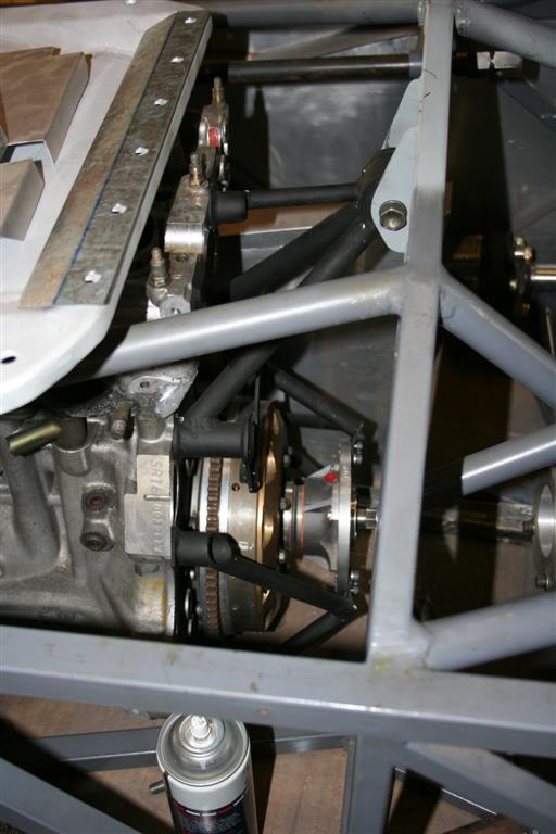
Very
slow progress,
but some progress of sorts. We sold the VVL SR16 head and got a more conventional cam-on-bucket type, as we were not convinced that the VVL gear would stay together at the 8500rpm the engine would be running at all the time. The rear suspension is basically done, as you can see. It's just a matter now of finalising the ride heights front and rear so we can make the links from the uprights to the rockers. The dampers are likely to be Koni 2812 Mk2 L versions. |
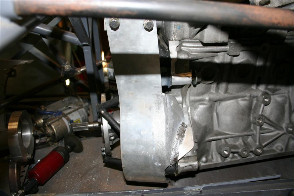 |
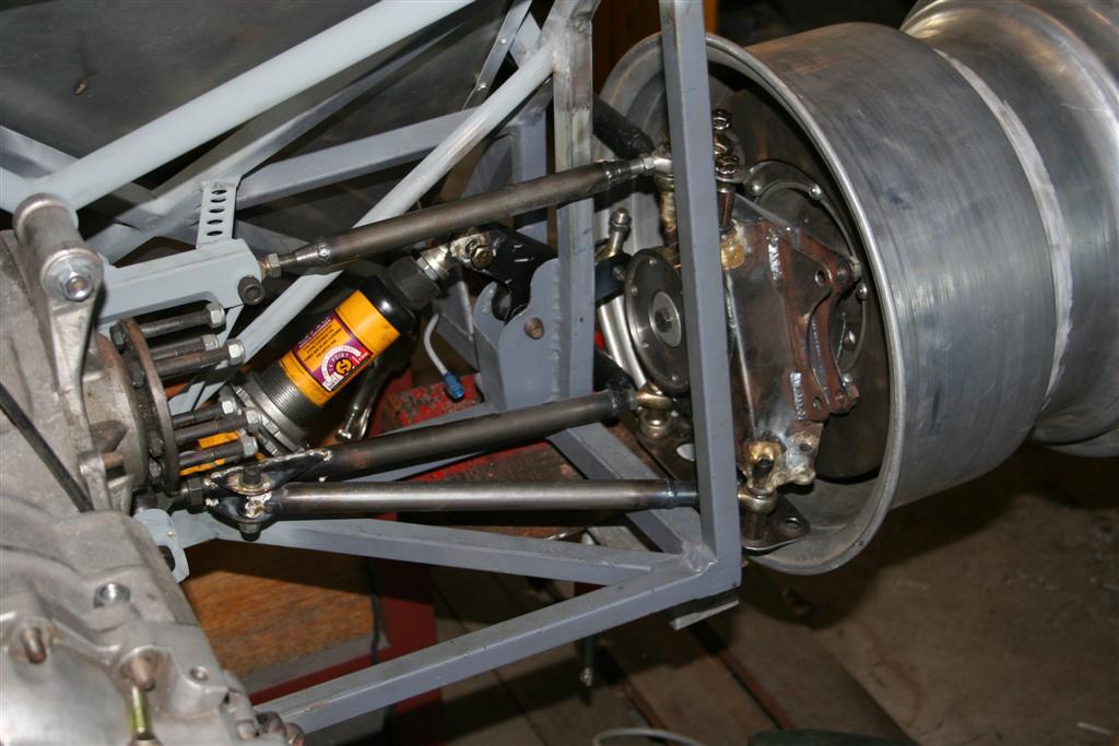
A
strong scatter
shield is needed around the flywheel in case it lets go, and parts from
it head towards my legs, which are scant inches away. We came up with
an elegant curved design that should work well - I hope it never has to! On the left of the photo is the tailshaft containment hoop, for similar reasons. Because the tailshaft doesn't move like a normal up, up & down, the hoop can be quite small though it needs unbolt so we can get the tailshaft in & out of the car. |
 |
We
had to choose
where to put the clutch - On the flywheel or on the front of the
gearbox. We decided to put it in the conventional place as it would
allow me to decouple the drive if something goes wrong, and then stomp
on the brakes to lock the rear to stop the drivetrain from turning. If
the clutch was on the rear then the engine would always drive the
tailshaft and so it could potentially flap around until the engine
stops. So here you can see the hydraulic centreline clutch used. The starter motor goes on a bracket on the top of the flywheel, to make it easy to get to if it fails. (they tend to a lot on race cars) |
We will
also be changing the bodywork to look more like a LeMans type car,
though this isn't a prority at the moment. We'll likely to just use the
current Mallock bodywork to start the testing.
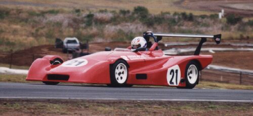
This is another view of what
it'll look like
when it's finished and the testing starts.
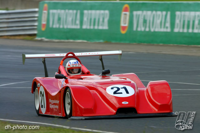
The new bodywork will look more like this though ->
For more motorsport links, try the motorsport section on my links page.
Back to the Index page
Page & contents where applicable © Bill Sherwood